
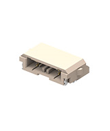
Board to board connectors
High quality and competitively priced PCB connectors for any situation. With over 160 standard parts in the GCT Board to board range and a large element of customisation also available. Pitches ranging from 0.8mm to 5.08mm, selectable pin lengths, and insulator heights. Other features include locating peg options, shrouding, polarisation, keyed or elevated headers and sockets, with completely bespoke solutions possible.
Board to board connectors are designed to connect printed circuit boards together without a cable. This connection can be permanent in the case of "hard soldering" (soldering a pin header to the PCB at both ends). This approach may be used in a "fit and forget" solution where no mating cycles are required.
However, in most applications the printed circuit boards are required to be connected and disconnected to simplify assembly and allow design flexibility. Pin headers (male) and socket (female) connectors are used as a
pair, one mating and unmating is described as a "mating cycle".
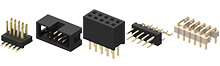
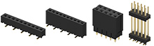
Broadly speaking, board to board connectors are manufactured in the following types:
aka
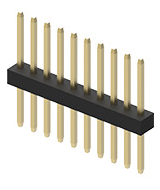
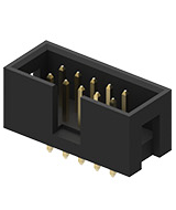
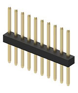
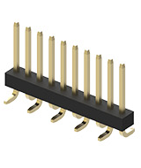
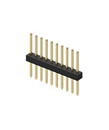
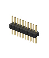
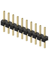
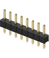
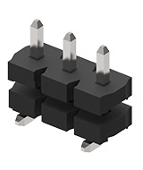
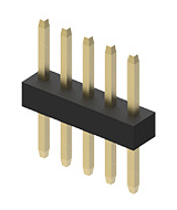
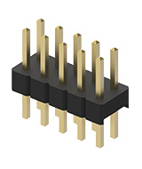
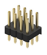
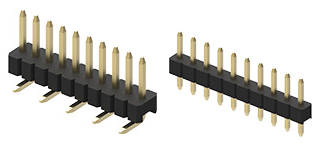
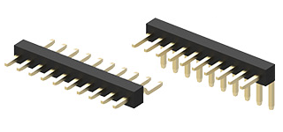
Male Header
aka
Stacked
Stacker
Mezzanine
PC104 Header
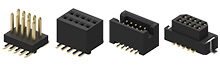
aka
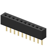
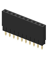
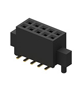
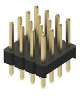
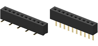
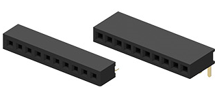
Female Header
Receptacle
aka
Stacked
Stacker
Mezzanine
PC104 Socket
aka
Box Header
GCT board to board connectors are available in through hole (TH) and Surface Mount (SMT) variants.
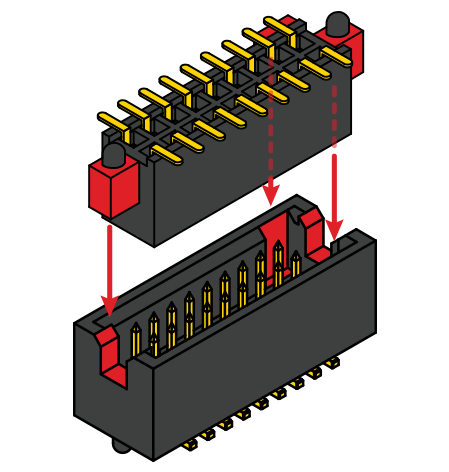
Locating pegs (also referred to as locating posts, alignment pins or board locks) are used to assist alignment of connectors to the PCB. Locating pegs are particularly useful when using surface mount components.
Pitch refers to the spacing between individual pins. There are numerous considerations the hardware designer must balance in choosing the correct connector pitch:
Space constraint - The smaller the pitch, the smaller the connector. Generally using smaller pitches allows lower connector profiles and thus lower printed circuit board stacking profiles. However, GCT offer numerous low profile connector options across all pitches.
Current carrying capacity - the smaller the header pin size the lower the current carrying capacity.
Other physical constraints - does the range offer the connector types to achieve the design you require? e.g. there are sixty seven 2.54mm connector options and nineteen 1.00mm options, so depending on your design you're more likely to find a physical solution in the numerically larger ranges. That said, the small ranges cater for the most basic designs, such as PCB's mating in co-planar, right angle and parallel orientations.
GCT board to board connectors are available in the following pitches:
(.031"x.047")
(.039")
(.050")
(.079")
(.100")
(.156")
(.157")
(.200")
For experienced hardware designers choosing board to board connectors is second nature, for the uninitiated it can be daunting. We offer design support and will help guide you through the options available. If you need help with your board to board connector design, contact GCT. Where required GCT also offer non standard pitches, you can see an example on our custom connector page.
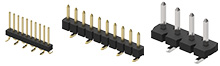
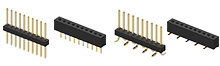
GCT offer headers are receptacles in single, dual, triple and quad row configurations. Single and dual row are popular choices, while triple and quadruple row are offered in a smaller number of pitch and style options.
Dependent on the your application, PCB's can be oriented in a variety of ways:
aka
Mezzanine
Stacked
Sandwich
aka
Planar
Side-by-Side
Butt-Ended
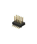
aka
Right Angle
Daughter Card
Vertical
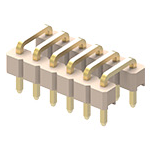
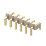
aka
Economical alternative for LED connector strips
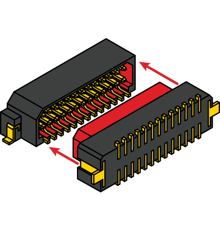
In order to cater for differing PCB orientations, different board to board connector orientations have been developed to suit. In most application a pin header and socket would be used as a pair ro simplify assembly and allow disconnection/reconnection (mating cycle) as required.
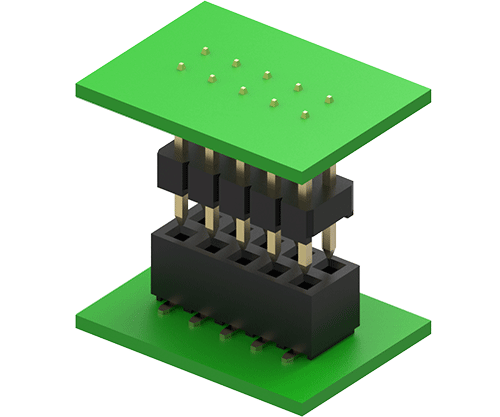
To achieve a connection between a pair of parallel PCB's only one part combination can be used:
- Straight pin header and straight socket
To achieve a connection between a pair of horizontal PCB's only one part combination can be used:
- Right angled pin header and right angled socket
To achieve a connection between a pair of perpendicular PCB's, two combinations could be used:
- Straight pin header and right angled socket
- Right angled pin header and straight socket
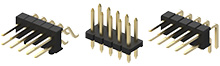
Here are some examples of board to board pin and contact options.
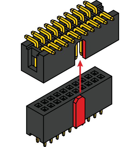
Voided Pin
 Larger pitches can be created by selective loading (i.e. a
.100 (2.54mm) pitch pin header with every 2nd pin omitted = .200 (5.08mm) pitch). Voided pin (also known as selective loading or polarization)
can be applied to all types of board to board connector.
Larger pitches can be created by selective loading (i.e. a
.100 (2.54mm) pitch pin header with every 2nd pin omitted = .200 (5.08mm) pitch). Voided pin (also known as selective loading or polarization)
can be applied to all types of board to board connector.Voided Contacts
 As with the voided pin but with reference to sockets (also known as voided contact or polarization).
Post and tail length
Post length (also known as post height) is the length of pin above the plastic insulator that mates with the socket (only applicable to pin headers):

Tail length is the length of pin below the insulator that is used to solder to the PCB. Tail length is applicable to pin headers and sockets but only in through hole format:


Post or pin size (mm²)
Post/pin size is the cross section of the conductor measured in mm².
Each different pitch has a different post size:
- .039" (1mm pitch) = 0.30mm²/0.012”²
- .050" (1.27mm pitch) = 0.40mm²/0.016”² or 0.46mm²/0.018”²
- .079" (2mm pitch) = 0.50mm²/0.020”²
- .100" (2.54mm pitch) = 0.64mm²/0.025”²
- Custom connector – GCT design & manufacture board to board connectors to suit customer specific applications
Kinked Pins
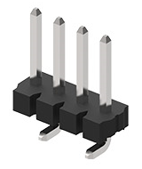
Kinked pins (also known as locking leads) are used as a method of fastening a through hole pin header or socket to a PCB prior to soldering.
Kinked pins are particularly useful when using tall components and/or wave soldering process that may cause the connector to move out of position before it can be soldered in place.
Example of a kinked PCB header pin:

Contact Type
GCT manufactures 4 types of contacts for use in sockets:
- Stamped tuning fork
- Dual beam spring contact
- Triple beam spring contact
- Four sided spring contact
Please see individual datasheets for contact types used in each range.
Profile Above PCB
A good starting point when calculating PCB connector stacking is to calcualte the board to board connector height. This is measured from the printed circuit board face to its highest insulator point above the PCB is known as its profile. See some examples below:

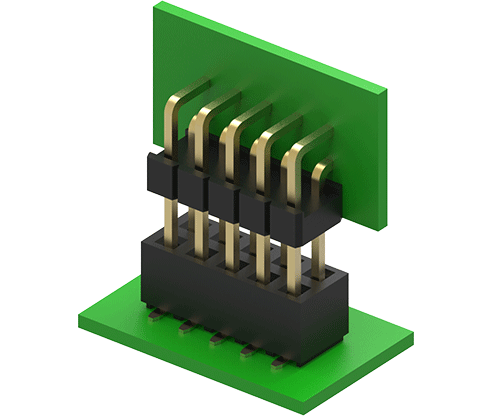
Parallel PCB Mating - Elevated Headers
When an exact distance is required between PCB's it is common to use a stacking pin header and female socket arrangement.
For example, if a PCB separation distance of 20mm is required a 5.00mm profile socket and 15mm stacking height elevated pin header could be used. This is only an example as in the GCT board to board connector range we have connectors with a variety of insulator profiles, depending on connector pitch.
Please note, 1mm board to board elevated headers variants are not suitable for load-bearing applications. The insulator should be used to aid pin alignment only and additional mechanical support for the PCB is recommended. GCT can offer load-bearing solutions if needed, such as this customised example seen here. Please contact us to discuss the best solution for your application. Please contact us to discuss the best solution for your application.

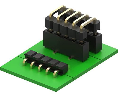
Parallel PCB Mating - Elevated Sockets
An alternative to stacking headers. Why customers choose stacking sockets:
- Isolation - contacts encased in shroud.
- Stacking solution required - design of PCB header is out of customers control. e.g. Off the shelf wireless module PCB.
- Superior strength vs stacking header.
- If two stackers are used then one elevated header and socket will polarise.

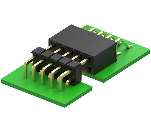
Parallel PCB Mating - Bottom Entry Sockets
Also known as pass through, allows mating with a pin header from the underside of the PCB rather than the top side.
When bottom entry sockets are used, holes are drilled in the PCB to allow the pin header to pass through.
Example of a bottom entry, SMT socket PCB layout:
KEY
 SMT Pads
 Drilled holes to allow header pins to pass through
 Drilled holes for locating pegs

Customers choose bottom entry sockets to reduce distance between stacked PCB's, or to allow use of a single sided PCB.
In order to select the correct header mating pin length customers must provide PCB thickness (for example 1.6mm/.062"), the PCB thickness must be taken into account to calculate the total distance to the mating point. GCT receptacle drawings show the mating points.

This section covers connector contact material and plating within GCT's board to board connector range. Core header pins & receptacle contacts are manufactured using high quality copper alloy, this material is cost effective, easy to manufacture with good electrical properties.
Metal plating layers are added to the core pin or contact to allow or improve:
- Corrosion resistance
- Wear resistance
- Solderability
- Electrical performance
- Temperature protection
- Appearance
All pins and contacts are under-plated with a layer of nickel to:
- Provide wear and corrosion resistance
- Resist migration of materials between the base material and finish plating
Finish plating is available in variants of gold or RoHS compliant tin
- Tin offers excellent solderability and conductivity, but low durability - low cost
- Gold offers excellent conductivity, low resistance, excellent corrosion resistance and durability - high cost
- GCT's gold flash plating offers a good balance between the advantages of gold and the lower cost of tin.
GCTs range of board to board connectors are available in a variety of packaging options as standard:
- Loose in bag or box
- Tray
- Tube
- Tube with pick and place (P+P) cap or film
- Tape and reel (T+R) with pick and place (P+P) cap or film
Custom packaging is available. For example, through hole connectors in tape and reel packaging for paste in hole applications. Contact us to request a custom packaging option.
See images below for some packaging examples. More information is available on specific product datasheets.


Tape and Reel Packaging for SMT Components
GCT's SMT headers offers customizable mating pin lengths and each series has a choice of multiple numbers of circuits. This adds up to thousands of individual part number combinations per connector series.
It's important for connectors to be packaged within correctly sized cavities in the tape and reel carrier strip, the correct height, width and depth cavity to house the header and cap keeps parts in a secure and consistent position during transportation. Once connectors reach the production line they should be presented for pick and place process in a consistent and stable manner.
GCT offer a range of custom Tape and reel carrier strip packaging cavities. One T&R cavity can accept more than one circuit size, however, given the number of connector variations not all cavities are tooled.
The examples below show headers, SMT sockets are also offered in multiple cavity sizes, the height and footprint of sockets may often be fixed, but width is a custom variable dependent on circuit size.

Customers may also choose T&R packaging for thru hole component used in a paste in hole production process.
Contact your local GCT sales office to discuss your PCB connector packaging requirements.
GCT's range of polarized connectors for board to board applications offer a variety of options. Customers may choose from a range of pitch sizes, each having their own method of assuring that mating headers and sockets may only be plugged together in the correct way. All options include shrouding and keying designed into insulator on the male and female mating halves.
Why use polarized connectors?
- Eliminates connector mis-mating, which depending on where power is routed can avoid costly damage to OEM equipment.
- Allows multiple connectors to be used on one piece of equipment, customers may choose to use different polarized circuit sizes, such as a 10 and 20 position to clearly identify which orientation a mating PCB is designed to plug together.
- Aids blind mating, where the installer or end user cannot see the connection to be made, and has to feel for the connection.
- Helps prevent damage to exposed header posts (.050" & .1" pitches).
Range by Pitch
1.00mm Pitch
The keyed and molded BC060 & BC061 offer a tiny, surface mount, polarized connector option for parallel PCB mating configurations, available in 10-30 circuits.
1.27mm Pitch
Polarization is achieved by a different sized cut out at each end of the male header, the female connector include two end pieces which mate perfectly with the header cut outs. In addition there is an offset sideway key. There are options in this range to mate PCB's in parallel and right tangle orientation. An elevated stacker header offers other design choices for stacking polarization.
2.54mm Pitch
A Central bump system similar to traditional IDC connectors prevents header and socket being mismated. Headers are keyed while the receptacle has a sidewall bump.
Be in the know about product launches, promotions and more
Useful
Support
Global headquarters
GCT Limited
GCT Inc
GCT Hong Kong Ltd
Regional offices

Copyright © 2024 GCT (Global Connector Technology) All Rights Reserved